INTRODUCTION
SECTION I - Tools
SECTION II -Shutter
Operation 1: Access to Shutter
Assembly
Operation 2: Removal of Shutter
Assembly
Operation 3: Spring Replacement in
Shutter
Exposure Button Spring
Shutter
Spring
Operation 4:
Changing Exposure Button
Operation 5: Cleaning and Easing
Shutter Movement
Operation 6'. Replacing
Shutter
SECTION III -
Camera Front Assembly
Operation 7'. Replacement
of Camera Lens
Operation 8". Replacement of
Viewfinder Mirror
Operation 9: Replacement of
Viewfinder Box
Operation 10: Replacement of Viewfinder
Front Lens
Operation 11: Cleaning
Lenses
SECTION IV -
Body
Operation 12: Replacement of Viewfinder
Top Lens
Operation 13: Replacement of Winding
Key
Removal of
Key
Replacement of
Key
SECTION V-Camera
Back
Operation 14: Removal of
Back
Operation 15: Replacement of
Back
Operation 16: Replacement of Back
Latch
SECTION VI-Roll
Holder
Operation 17:
Replacement of Guide Roller
SECTION
VII-Close-up Lens (Model D)
Operation 18: Removal of Close-up
Slide
Operation 19:
Replacement of Close-up Slide
SECTION
VIII-Close-up and Filter Assembly
(Models E & F)
SECTION IX-Flash
Contacts (Models D, E and F)
SECTION
X-Service Part List
SERVICE MANUAL
FOR SIX-20 'BROWNIE'
The original "Service Manual for SIX-20 'Brownie' Cameras with All-metal Welded Bodies" covered the Models C & D with
no flash contacts, and Model E with flash contacts.
Since
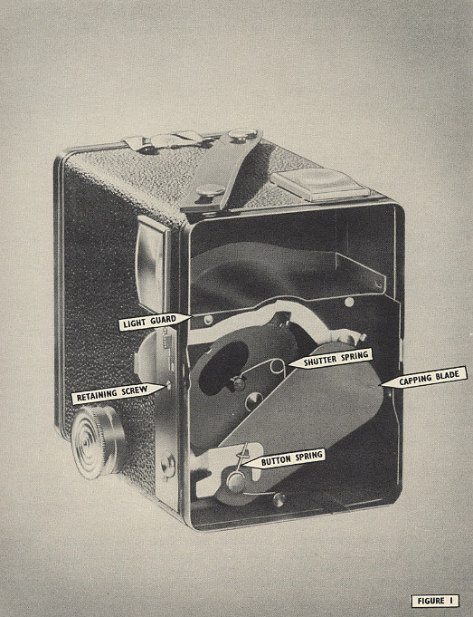
the issue of that manual, the Model D has had flash contacts added, these being of the same type and setting as on the first
Model E. Figure 1 illustrates the earlier Model D.
With
the introduction of the Model F, new flash contacts were incorporated which allowed the use of either F or M types of
flashbulb.
At
the same time the contacts on the Models D and E were modified to match those of the Model F.
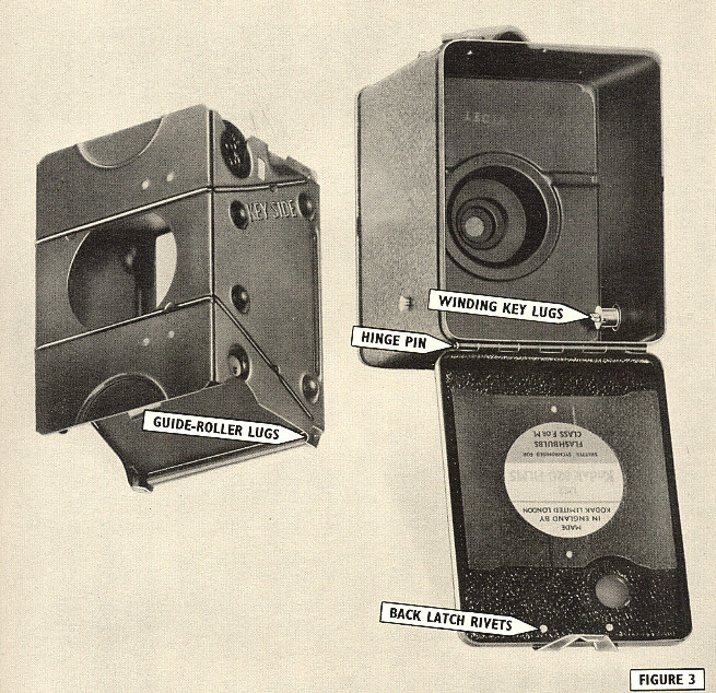
These
later Models D and E have a label, bearing the words-"Shutter synchronized for flash bulbs Class F or M"- fixed to the inside
of the back (see Fig. 3).
This
service manual covers all models, and the appropriate servicing of flash contacts is referred to under Section
IX.
A
further alteration to the Models D, E and F is the use of engraved figures in place of the words "Close-up" or "Portrait" on
the close-up slide.
In
the text, "Close-up" has been used throughout, but the instructions apply equally to those cameras bearing on the slide the
word "Portrait" or the engraved figures.
SECTION-I
TOOLS
For the servicing
outlined in this manual, the following tools and supplies are required:-
4oz.
Hammer.
4½" Pliers, Snipe
Nose.
4½" Pliers, Flat Nose.
Tweezers, Watchmaker's
"A.A."
3/16" Screwdriver-Fluted
Handle.
Flat-headed Punch.
"Turn-over" Rivet Punch.
'Selvyt' Cloth.
Camel-hair Brush.
Lens Cleaner.
Dry Powdered Graphite.
Cellulose Dead-black Paint.
Hand Drill with assorted small-gauge
drills.
'Seccotine' or similar
glue.
In addition to the
above general tools and supplies, the following special tools are required:-
Winding Key Jig T.11.
Angle Rivet Punch T.16.
These special tools
are available from:-
Kodak Limited, Equipment Services, Wealdstone, Harrow, Middlesex.
The shutter is a new
type employing several departures from normal 'Brownie' practice. It is a simple, robust and efficient mechanism of few
parts. This makes servicing easy, and no difficulty should be experienced in carrying out the following
operations.
Operation l:
Access to the Shutter Assembly
Hold
the camera front firmly between the fingers and thumb of one hand, and hold the body of the camera with the other
hand.
Ease off the front plate assembly, first lifting the side nearest to the exposure button. The assembly
consists of the camera lens, the viewfinder front lens, and finder boxes with their mirrors.
With the front plate removed, access is obtained to the shutter assembly.
Operation 2:
Removal of the Shutter Assembly
See
Fig. 1. Lift the right-hand edge of the light guard on the top of the shutter bracket. It is "sprung" into place
and once clear of the indentations on the camera box side can be easily withdrawn.
In
some later models., the lip on the shutter bracket and the hood on the guide channel have been lengthened, thereby obviating
the necessity for the light guard. In these models the light guard has been omitted.
(If
servicing Models D, E and F, unscrew the three retaining screws of the instruction plate at the left side of the camera and
remove the instruction plate. Do not lose the shutter-lock lever from the Models E and F).
Place
a finger behind and on the right-hand side of the shutter bracket and pull towards the front. At the same time ease the
right edge of the bracket over the retaining stud in the right-hand wall of the camera box.
This will release the
whole of the shutter assembly.
Operation 3:
Spring Replacement in the Shutter
See Fig. 1. There are two springs, (a) Exposure Button Spring
Lift the end of the spring from the grooved anchor stud at the bottom center of the shutter
bracket.
Lift
the coil of the spring off the capping blade stud upon which it pivots. Remove the spring, sliding out the upper end
from the drilled lug attached to the capping plate.
Insert the short end of the new spring
into the drilled lug
of the capping plate. Ease the coil of the spring over the
pivot
stud. Hook the long end of the
spring into the groove of the
anchor stud.
(b) Shutter
Spring
This
spring is attached (a) to the rear of the capping blade, and (b) to the front of the shutter. It is possible to remove
the spring ends from both anchorages by manipulation with a pair of tweezers.
Press the exposure
button and keep it pressed. This will bring into view the spring stud of the shutter. Lift off this end of the
spring, noting carefully the fixing arrangements.
Allow
the spring to straighten and hang from the capping blade stud. Steady the loose end of the spring with the thumb, and
push the opposite hooked end off the capping blade stud, using a small screwdriver. If difficulty is experienced, it is
permissible to bend the capping blade forward slightly in order to gain access to the spring anchorage.
When
replacing the spring, first attach it to the capping blade, then, with the exposure button pressed, fix the other end to the
shutter. The arms of the spring must exert an "outwards" force. Note that the loop or coil of the spring should
be pointing away from the exposure button when the button is pressed.
Do
not forget to re-align the capping blade before putting the shutter back into service. A piece of rod or circular wood
held underneath the point of bending will prevent excessive distortion.
Operation 4:
Changing the Exposure Button
See
Fig. 1. Remove the exposure button spring, as in Operation 3. Lift the plate of the exposure button away from the
drilled lug of the capping blade and slide out the exposure button from the side of the assembly.
Insert the new exposure button so that it projects through the hole provided. See that the triangular slot engages
with the drilled lug of the capping blade with the plate lying flat, and movement of the button correctly transmitted to the
capping blade.
Replace the exposure
button spring.
Operation 5:
Cleaning and Easing the Shutter Movement
To
ensure smooth working of the shutter, clean the INNER surfaces of the shutter plate and blade with a camel-hair brush and
polish with dry powdered graphite. Do not use oil.
Operation 6:
Replacing the Shutter
Reverse the procedure
outlined in Operation 2.
SECTION III - CAMERA FRONT
ASSEMBLY
Operation 7:
Replacement of the Camera Lens
Remove camera front
complete, as in Operation 1.
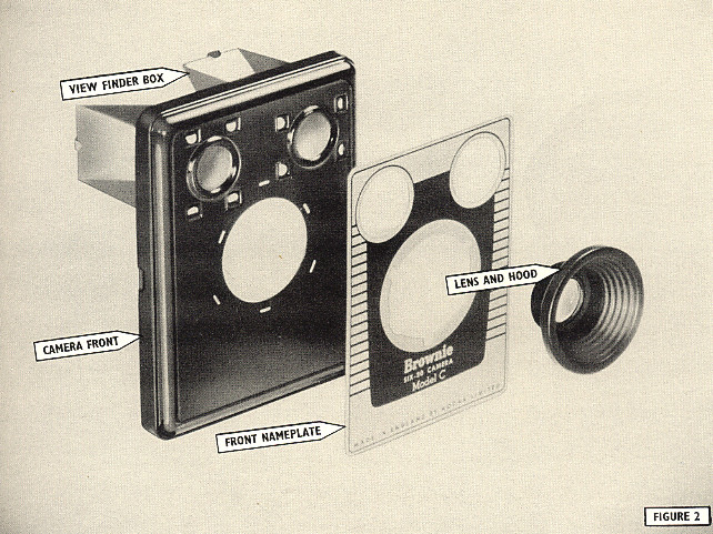
See Fig. 2. Lay
the front, face down, on a dust-free surface and lift the securing lugs of the lens and hood assembly. With the lugs
straightened, withdraw the lens and hood. This will also release the front name plate.
Insert the new center
lens complete with hood, and guide the lugs of the hood into their slots. Bend over the lugs with pliers and then tap
them flat, using a flat-headed punch. Make sure that the name plate is centered correctly.
Operation 8:
Replacement of the Viewfinder Mirror
Insert a screwdriver into the top of the finder box and lift the two mirror retaining lugs, thus freeing the mirror.
Remove it, and replace with a new one. Turn down the retaining lugs and flatten them with the aid of a
screwdriver.
Operation 9: Replacement of
the Viewfinder Box
Remove the camera lens
and front plate, as in Operation 7. The four lugs securing each box can be seen projecting through the camera front.
Taking care not to drop the viewfinder front lens, lift these lugs, straighten them, and then withdraw the finder box.
Fit a new box, trapping the lens in position, flat side towards the camera front, and flatten the retaining
lugs.
Operation 10:
Replacement of the Viewfinder Front Lens
Remove the finder box as in Operation 8. This automatically releases the front lens of the finder. To
replace, merely insert a new lens with the flat side towards the camera front, and trap it in position by fastening down the
finder box lugs.
Operation 11:
Cleaning the Lenses
First remove any surface dust or grit, using a soft clean camel-hair brush. Polish with a 'Selvyt'
Cloth, using a light rotary motion. If the lens is very dirty, use a little 'Kodak' Lens Cleaning Solution on the
cloth. Do not use acids, alcohol or harsh linty cloth. Avoid excessive pressure and unnecessary
cleaning.
SECTION IV -
BODY
See
Figs. 1 and 3. If the body structure itself is damaged, repair is not possible, and a complete replacement of the case
is necessary. The following repairs to case fitments are practicable:-
Operation 12:
Replacement of the Viewfinder Top Lens
Remove the camera front
complete as in Operation 1.
With a screwdriver,
lift the lugs securing the top viewfinder lens retainer.
Straighten the lugs and withdraw the viewfinder lens retainer. The top lens of the finder can now be removed and
replaced. Refasten the retainer by means of the four lugs, making certain that the lens is gripped tightly in
position.
Operation 13:
Replacement of the Winding Key
(a)
Removal of the Winding Key
Slide the disc of the
winding key into the slot provided on the winding key jig. Open the camera back, withdraw the roll holder and, using a
screwdriver, rise up the two lugs securing the key.
Straighten the lugs and
withdraw the key.
(b)
Replacement of the Winding Key
Remove the old key from the jig and replace with a new one. Insert the lugs of the key into the slots in the camera side
and press home with the winding key still held in the jig. Bend the lugs outwards and tap flat with a small
hammer.
SECTION V - CAMERA
BACK
Operation 14:
Removal of the Back
See Fig. 3. Unlatch the back, and using a piece of stiff wire as a punch, tap out the hinge pin
until it projects sufficiently for a grip to be obtained with the pliers.
Using the pliers, withdraw the hinge pin. The back is now free.
Operation 15:
Replacement of the Back
Align
the hinge pieces of the new back with those of the camera body. When they are in register, insert the hinge pin, using
pliers. If inclined to be stiff, lightly tap home the pin with the hammer.
Operation 16:
Replacement of the Back Latch
Remove the camera back,
as in Operation 14.
Use a drill slightly smaller than the rivets securing the latch to the camera back, and drill out the
rivets.
Withdraw the rivets and
the defective latch.
Position the new latch with rivet holes in register. Insert new rivets with the heads on the outside of the camera
back. With the round heads backed by a flat metal surface, use a punch (spread-over type) to turn over the ends of the
rivets.
Replace the camera
back.

SECTION VI -
ROLL-HOLDER
If
the roll holder is damaged structurally, it must be completely replaced. The rollers may be removed and cleaned, if
necessary, and the interior of the roll holder may sometimes require "touching up" with dead-black paint. Oil must not
be applied to the guide rollers; if they show any signs of corrosion they should be replaced.
Operation 17:
Replacement of a Guide Roller
See
Fig. 3. Bend out the drilled lugs holding the guide roller in place. The lugs should be bent no more than is
necessary to remove the roller.
Replace with the new roller. Bend back the drilled lugs forming the bushes at either end of the roller in such a
way as to give maximum freedom of the roller to revolve with minimum end-play. If there is any stiffness in working,
the application of a little powdered graphite to the ends of the rollers will ease them considerably. Oil must not be
used.
SECTION VII - CLOSE-UP LENS Model D only
Damage to the close-up lens is unlikely, but in this event, replacement can be carried out as
follows:-
Operation 18:
Removal of the Close-up Slide
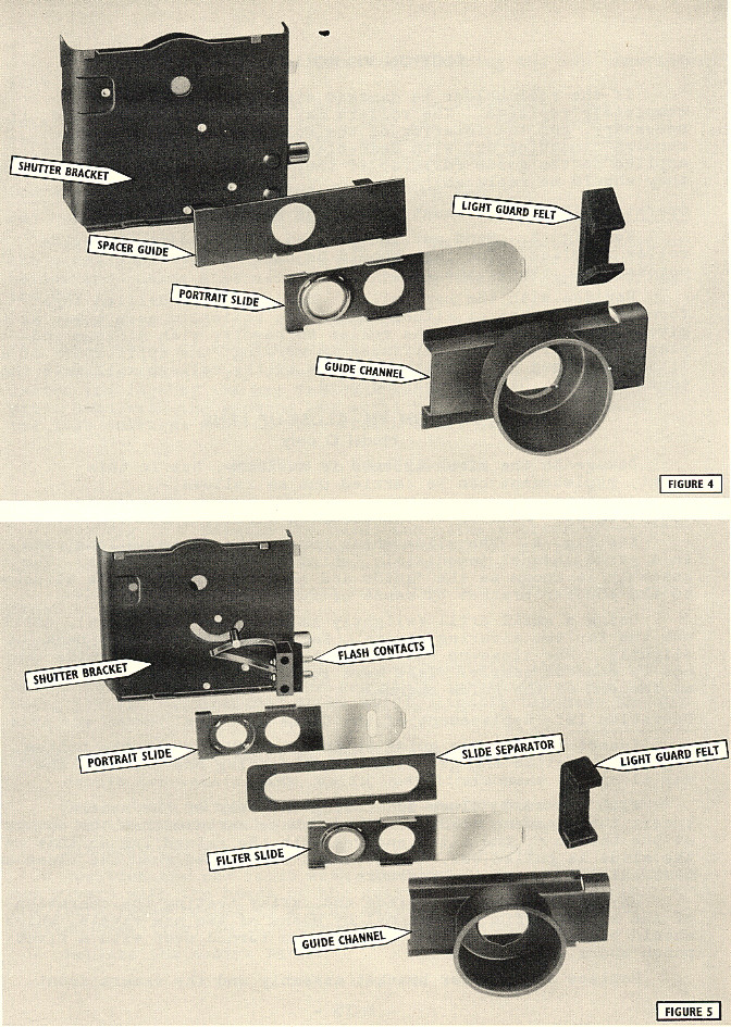
See
Fig. 4. The slide which houses the close-up lens runs in a guide channel immediately behind the shutter bracket.
The assembly is known as the "guide and hood assembly" and is attached to the shutter bracket by means of four
rivets.
Using
a small drill (slightly smaller than the rivet), drill out the top two securing rivets. Ease the guide channel back
slightly. The close-up slide assembly and the spacing guide can now be removed easily. Take care to retain the
light-trap felt at the end of the guide channel.
Operation 19:
Replacement of the Close-up Slide
Insert the spacing guide so that the "V" cut on the bottom edge of the slide engages with the raised lug
one third of the way along the channel.
With
the word "Close-up" facing the rear of the camera, insert the close-up slide assembly. Make certain that the cut-out at
the bottom of the slide engages with the raised lug so that as the slide is pulled out, the movement is checked when the
close-up lens exactly covers the aperture.
Re-position the felt piece and, after testing the operation of the slide, refix the channel by means of two new rivets,
which should be backed by a metal surface and turned over with a rivet punch and a small hammer.
Replace the shutter
bracket assembly and the camera front.
SECTION VIII -
CLOSE-UP AND FILTER ASSEMBLY
Models E and F
The close-up and
filter assemblies on these models are fitted in a similar manner to those of the SIX-20 'Brownie' Model D. The spacing
guide differs slightly in construction, however, due to the additional space occupied by the filter slide, (See Fig.
5).
Servicing should be
carried out as detailed in Section VII, but it should be noted that the slides are inserted with the words "Close-up" or
"Filter" to the FRONT of the camera and not to the rear, as in Model D.
SECTION IX - FLASH CONTACTS
Models D and E synchronized for class F flashbulb only
The flash contacts of these models can be tested for synchronization as detailed in the Kodak Equipment
Services Manual "How to use the 'Brownie' Flash Tester".
Model F, and Models
D and E synchronized for class F and M flashbulbs
With
these cameras, the flash contacts have been modified to give a long "wipe". As a result the 'Brownie' Flash Tester
cannot be used with these cameras to give any accurate indication of the point at which flash contact is made.
The
neon indicator of the Flash Tester will give a definite indication whether or not contacts are making. As the contacts
are accurately.set during manufacture to cover a flash delay up to 25 milliseconds, it is reasonable to assume that if
contact is being made, the camera shutter will satisfactorily fire all types of flashbulb.
Should there be any doubt as to the efficiency of the flash contacts, the camera should be returned to Kodak Limited,
Equipment Services, for checking on an electronic shutter tester.
SECTION X-SERVICE PART
LIST
When
ordering service parts, the part numbers must be quoted.
|
MODEL C
|
No.
|
MODEL D Cont.
|
No.
|
|
Camera Front Complete
|
D.3387
|
Guide for Slides with
Hood
|
D.3378
|
|
Front and Finder Box
Assembly
|
D.3383
|
x
|
x
|
|
Centre Lens Mounted Front
Plate
|
D.3390
D.3079
|
Slides in Guide
Assembly
|
D.3401
|
|
Camera Front Finder Box
Front Finder Lens
|
D.3007 D.3028
D.3026
|
Spacer for Slide Felt
for Slide Portrait Slide Assembled
|
D.3070 D.3049
D.3429
|
|
Finder Mirror
|
D.3027
|
MODEL D with Flash Contacts
|
|
|
Camera Case Complete
|
C.3373
|
Camera Front
Complete
|
D.3386/D
|
|
Key Complete
|
D.3398
|
As for Model D
except-
|
|
|
Top Finder Lens
|
D.3025
|
Front Plate
|
D.3397
|
|
Top Finder Lens
Retainer
|
91001
|
x
|
x
|
|
Handle
|
D.3018
|
Camera Case Complete
|
D.3385
|
|
x
|
x
|
Side Instruction
Plate
|
D. 13394
|
|
Camera Back Complete
|
D.3392
|
Screws for above
|
D.3118
|
|
Back Latch
|
93660
|
x
|
x
|
|
Rivets for above
|
D.3030
|
Camera Back Complete
|
D.3392
|
|
Hinge Pin
|
D.3032
|
Back Latch
|
D.5758/A
|
|
Red Disc (celluloid)
|
1618
|
Rivets for above
|
D.3030
|
|
Red Window
(celluloid)
|
D. 13265
|
Hinge Pin
|
D.3032
|
|
x
|
x
|
Red Disc
(celluloid)
|
D.1618
|
|
Shutter Assembly Complete
|
C.3382
|
|
|
|
Time Lever
|
90997
|
Shutter Assembly
Complete
|
D.3388
|
|
Time Lever Stud
|
D.3057
|
Time Lever
|
.3056/A
|
|
Exposure Button
|
90998
|
Time Lever Stud
|
D.3057
|
|
Exposure Button
Spring
|
D.3052
|
Exposure Button
|
D.10500
|
|
Light Guard
|
D.3038
|
Exposure Button
Spring
|
D.3052
|
|
Shutter Spring
|
99802
|
Portrait Slide
Assembled
|
D.3429
|
|
x
|
x
|
Felt for Slide
|
D.3049
|
|
Roll Holder Complete
|
91773
|
Spacer for Slide
|
D.3070
|
|
Guide Roller
|
91604
|
Contact Spring,
Upper
|
D.3405
|
|
x
|
x
|
Contact Spring,
Lower
|
D.3406
|
|
x
|
x
|
Contact Block
|
D.3402
|
|
MODEL D
|
x
|
Contact Pin
|
D..3404/D
|
|
x
|
x
|
Contact Pin Nut
|
N.1800
|
|
Camera Front Complete
|
D.3386
|
|
|
|
As for Model C
except-
|
|
Roll Holder Complete
|
91773
|
|
Front Plate
|
D.3077
|
As for Model C
|
|
|
Camera Case Complete
|
C.3372
|
MODEL E
|
|
|
As for Model C
except-¦
|
x
|
x
|
|
|
xx
|
|
|
Side Instruction
Plate
|
D.3075
|
Camera Front
Complete
|
D.3384
|
|
Screws for above
|
D.3118
|
As for Model C
except-
|
|
|
x
|
Front Plate
|
D.3008
|
|
Camera Back Complete
|
D.3392
|
Centre Lens
Mounted
|
D.3389
|
|
As for Model C
|
x
|
x
|
|
|
x
|
Camera Case Complete
|
D.3370
|
|
Shutter Assembly Complete
|
C.3381
|
As for Model C
except-
|
|
|
As for Model C
except-
|
|
Side Instruction
Plate
|
D.3022
|
|
Slides in Guide
complete
|
D.3401
|
Screws for above
|
D.96045
|
|
Rivets for above
|
96259
|
Key
|
D.3396
|
|
Roll Holder Complete
|
91773
|
Camera Back Complete
|
D.3391
|
|
As for Model C
|
x
|
As for Model C
|
x
|
|
Shutter Assembly
Complete
As for Model C
except-Exposure Button
Roll
Holder Complete
As for
Model C
Guide
for Slide with Hood
Slides in Guide Assembly
Spacer for Slides
Felt for Slides
Portrait Slide Assembled
Filter Slide Assembled
Flash Contact Mechanism
Contact Spring, Upper
Contact Spring, Lower
Contact Block
MODEL F
Camera Front Complete
Front and Finder Box Assembly
D.14711
Centre Lens Mounted
Front Plate
Front Finder Lens
Finder Mirror
Camera Case
Complete Key
Complete Top Finder Lens
|
C.3379
D.3427
91773
D.3378
D.3400
D.3065
D.3049
D.3375
D.3374
D.3405
D.3406
D.3402
D.14714
D.14715
D.14687
D.3026
D.3027
D.14712
D.14713
D.3025
|
Top Finder Lens Retainer
Handle
Side Instruction Plate
Screws for above
Camera Back Complete
Back Latch
Rivets for above
Hinge Pin
Red Disc (celluloid)
Red Window (celluloid)
Shutter Assembly Complete
Time Lever
Time Lever Stud
Exposure Button
Exposure Button Spring
Filter Slide Assembled
Portrait Slide Assembled
Felt for Slides
Spacer for Slides
Shutter Spring
Contact Spring, Upper
Contact Spring, Lower
Contact Block
Contact Pin
Contact Pin Nut
Shutter Lock Assembled
Roll Holder Complete
As for Model C
|
D.3029/E
D.14688
D.96045/E
D.14689
D.14718
D.5758/E
D.14723
D.3033
1618
D.13265
D.14720
D.3056/E
D.3057
D.14692
D.3052
D.14717
D.14719
D.5727
D.3065/E
D.99802
D.3405
D.3406
D.3402
D.3404/E
N.1800
D.14721
91773
|
Prices, which are
subject to Purchase Tax and normal discount, are listed in a separate Price List.
Address orders to Kodak Limited, Equipment Services, Wealdstone Harrow, Middlesex.
PRINTED IN ENGLAND: FEB.
I955
TP5628LL/800/255